
Lego orrery earth moon and sun
Обновлено: 02.05.2024
Help your fellow builder by leaving your feedback based on these three criteria:
- Originality: How original is this - never seen before?
- Building Techniques: How much skill do you think the creator of this MOC has, in terms of building technique?
- Details: Express how much you like the details of the build.
Your feedback is only shown to the creator as well as yourself. It is not available for other users to see. The creator won't see your user name.
Last Updated . Click "Updates" above to see the latest.
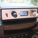
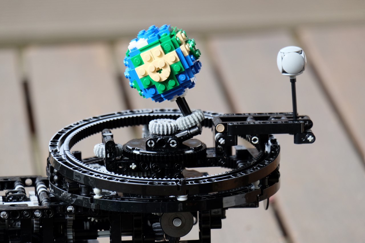
Everyone loves space. Whether its a beautiful sunrise, a brilliant starry night or even the immeasurable vastness of it all, everyone loves space! Bring space into your home with this kinetic model where the moon revolves around the earth, and the earth around the sun!
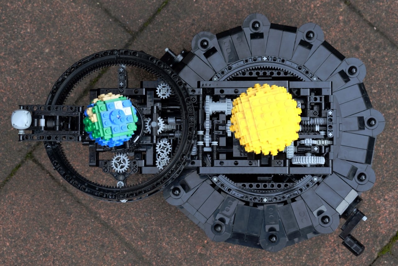
This build consists of the Sun, the Earth and the Moon, built on a vintage/antique style base. The Moon revolves around the Earth while the earth revolves around the Sun. The mechanics are hidden nicely inside the base. I have put a lot of effort into making the model as sturdy as I can, and the motion as smooth as possible. The model was built to look as nice as possible, with a detailed, brick-built version of the Earth.
The system is turned by a crank at the front, with minimal gears, that help it to turn smoothly. This does mean that the rotations aren't accurate, but I think it's more than worth it for the looks. It would require a lot of bulky mechanics to make it accurate!
As I've said already aim with this model was not to make a 100% accurate scientific model of an orrery, but rather to make something that looked great on display, while still being functional. I also wanted to make the design compact so as to keep it affordable. Another important aspect of this project was the varied build experience - a combination of Technic and System bricks to create an interesting and fun build.
- It's unique
- It would be a fun build experience
- It makes an amazing display piece
- It has a play aspect as well - the turning of the Orrery
- And on top of these it would be a great educational set - getting kids and adults alike interested in space!
This model would also have a very wide appeal - from space and astronomy fans to technic fans, as well as people who like collecting models for display. It would even appeal to an audience outside the LEGO community as it makes such a unique and impressive display model, helping draw new fans in.

Introduction: Sun, Earth and Moon Model (Tellurion / Orrery) With 3D Printed Parts


In this instructable I will describe the design and build of a mostly 3D-printable tellurion (a special class of orrery) which shows how the earth and moon revolve about the sun, about each other and how they rotate on their axes. I've always had an interest in these devices, both technical and aesthetic, but never previously had the time to complete one the old fashioned way (using a lathe & mill).
The device presented here stands about 20 cm high and sits on a 20 cm diameter wooden base. It is driven by a hand-crank (one turn per day) and can demonstrate the following phenomena:
- Daily rotation of the earth about its axis
- Earth's axial orientation fixed in relation to the celestial sphere, with an axial tilt of 23.4 degrees
- Revolution of the moon about the earth with 29.5 days (a synodic month) between each new moon
- Tidal locking / synchronous rotation of the moon with respect to earth (same face always facing earth)
- Moon's orbital plane inclined at 5.15 degrees to the ecliptic (plane of the earth's orbit round the sun)
- Precession of the lunar nodes on a 18.6 year cycle
- Position of the sun in zodiac throughout year (not technically rigorous - more for aesthetics)
It started life when I needed to help with a school project on the solar system. I created a simple 3D-printed kit that a child could assemble, which just modelled the motion of the moon round the earth as the latter revolved around the sun during the year. In the process I discovered that I could reliably 3D-print good quality large gears (known as 'wheels' to horologists). Nevertheless the kit was pretty crude and didn't generate the right number of synodic months in a year, so I set about improving it for my own satisfaction. Unfortunately it turned into a bit of an obsession for three months as I added and tested more and more complications (more horologist jargon). What you see here is the end result. There are still things that require improvement but better is the enemy of good enough.
There are a number of orrery / tellurion designs described on the internet but most seem to be incomplete or involve you paying for plans. On the other hand, attempting a project like this from a blank sheet is not for the faint-hearted. There are probably enough PLA gears etc. in my scrap bin to make another two of these (which won't work properly!). Anyway, I like to give back to the online maker community when I can, so I've attached all the STL files necessary to reproduce the device (except the lovely zodiac dial, which was designed by sully108 - details below). It's only fair to point out that even though most of the moving parts were made on a 3D printer, a considerably amount of fettling was required to get everything to fit together and work properly. If you choose to reproduce this work (note obligatory disclaimer: "at your own risk!"), you'll have a working thing of beauty to put on the mantelpiece and appreciate for years to come. Perhaps you'll make improvements and publish them in your turn.
IMPORTANT NOTE - this is a living document which gets added to as I or others make improvements. If you want to reproduce the tellurion, please read the whole document first (and probably some of the comments).
I've included a short (15 sec / 3 MB) .mov file of the tellurion operating, as a couple of people have asked. You'll need to download it and view it on a local application though.
Attachments
Step 1: You Will Need.
To build the tellurion you will need the following:
The following items are optional but will make life much easier if available:
- Lathe with tailstock-mounted Jacob's chuck (for cleaning up roughly-cut brass tube and for clearing out bores)
- Bench vice (for pressing bearings and gear shafts into 3D printed parts)
Step 2: Planning Out the Gear Ratios
The most important part of tellurion design is working out what all the gear ratios should be to reflect accurately the motions of the heavenly bodies. Superficially this is quite easy, but there is a trap for the unwary (which I fell into twice!). It arises because the axes of the gears modelling the earth and moon motions revolve once around the sun axis in one 'year', thus the attached celestial bodies will experience one rotation with respect to the sun even in the absence of those same gears. It's well worth doing your research thoroughly and not believing the first thing you read.
The majority of the moving parts in this model are mounted on a single curved 'orbit' arm tethered to the sun axis. (this being a throwback to the school project). I decided I wanted a simple hand-crank which would advance the model by one day for each clockwise rotation. The motion of the hand-crank is transmitted to the rest of the tellurion by a pair of bevel gears. In order to simplify the design, I opted to put the hand-crank at the moving end of the orbit arm, so it moves slowly round the baseplate of the tellurion as you operate it. The backplane for the crank helps to support the free end of the orbit arm, which carries all the gears.
The hand-crank turns a pair of bevel gears which drive all the motions of the tellurion via a 10 tooth gear.
Earth's rotation on its axis is one turn per turn of the crank, so the overall gear ratio is 1:1. The gear train is 10:10, 9:9.
The moon revolves round the earth once every 29.54 days (update 4/2020 - a mean synodic month is actually 29.53 days - that was my mistake but the error is small), which is achieved with a 10:50, 11:65 gear train. I know this because I used the excellent, no-frills Gear Train Calculator website which works out what the best gear choice for a given ratio is, given user constraints:
The earth-moon system revolves round the sun once every 365.25 days. This is easily achieved by extending the moon's orbit train. A ratio of 365.25 / 29.54 =12.36 is required, which is obtained by a small pinion on the moon orbit gear which engages with a much larger gear representing the solar orbit. The train is 11:136, which gives a ratio of 12.36. It is more efficient to extend the moon drive than to create a completely separate train of gears to go direct from the hand-crank to the solar orbit.
As the earth-moon system revolves round the sun during the 'year', a 'Ferguson mechanical paradox' arrangement of gears attached to the orbit arm (39:48:39) causes the earth's axial tilt to remain fixed with respect to the celestial sphere. Note that a classical mechanical paradox arrangement has three gears of the same diameter in a straight line. This isn't a strict requirement though and it was easier to put a larger gear offset from the line joining the other two.
A different output gear on the mechanical paradox arrangement is also responsible for rotating the inclined lunar nodes disc. The lunar nodes (where the moon's orbit passes through the ecliptic at two points) move retrograde at a rate of 19.36 degrees per year. Therefore the moon's orbital plane has to rotate once every 18.6 revolutions of the orbit arm. This is achieved using the 39:48:37 gear train.
The height of the moon is determined by the moon's position relative to the lunar nodes disc, by means of a push-rod on a radial arm which also serves to fix the moon's aspect relative to the earth.
It should be pointed out that the fact that the orientation of the earth's rotation axis is fixed with respect to the celestial sphere means that the earth would rotate once every year with respect to the sun, even if the earth did not rotate about its own axis. Thus the single turn of the hand-crank actually rotates the earth by one sidereal day (23 hours and 56 minutes) with respect to the sun, instead of a solar day (24 hours). This wasn't the first time I fell into this trap for the unwary, but as it corresponds to an error of only about 0.25% I decided it was acceptable for this application. In any case, to correct this would require four additional gears and I didn't think it was worth the effort. The first time I fell into this trap was for the school project, when I calculated the gear ratio of 365.25/27.5 for the moon's rotation (using a sidereal month of 27.5 days), which ignores the fact that the moon/earth system revolves round the sun once in a year. So I ended up with 13.4 lunar months in a year instead of the correct 12.4! Live and learn (slowly!).
The attached figure shows a schematic layout of the tellurion. The gears use the metric system (as do all other parts) and I've used a shorthand e.g. 136m1 to denote a 136-tooth module 1 gear. So for example 37m1054 is a 37-tooth module 1.054 gear; this is the only non-unity module gear in the whole set.
I used FreeCAD to draw the gears and other 3D-printed parts, and Cura to slice them for 3D printing. Even so, it took many attempts to get the right design, because many of the tolerances are critical when you are trying to mesh multiple gear trains on common axes. I frequently changed my mind about the best way to do things, too. The attached picture shows all the PLA parts that didn't make it into the final tellurion!
FreeCAD is a really good tool to use for this kind of work, because the distance between gear centres is always critical (and nothing else really matters). Therefore a constraints-based CAD tool is almost essential.Typically the work-flow would be:
- Determine the required gear ratio
- Print the gears (module 1, ideally)
- Mesh the gears on a depthing tool and determine the optimum centre separation (a simple one is shown here, based on a design in 'Making Clocks' by Stan Bray - once a nice separation is found the scriber points at the ends of the axles can be used to mark out the correct separation, on graph paper in this case)
- Enter the centre separation as a constraint in FreeCAD when designing the support structures (such as the orbit arm in this case)
- Print the support structure and test
Even with this procedure, further adjustment of centre separation might be required, particularly as more and more gears are added to the assembly and tolerances build up. That's why there's plenty of scope for generating scrap PLA during the design process. You'll note in the attached picture that there are five scrap orbit arms!
What's nice about this is provided you have all your gear centres correctly positioned on your cad package, the form of the support structure is totally up to you. I discovered by chance that all my centres lay broadly along an arc, which looked much nicer than the original rectilinear orbit arm (which resembled a wild west cactus by the time I'd finished!).
Step 3: Printing the Parts
Here are all the STL files needed to reproduce the moving parts of the Tellurion. The file names are mostly self-explanatory (I hope).
UPDATE - please also see the last page of this instructable, which contains revisions to some of the parts which you may or may not require, depending how your build goes.
It goes without saying that the 3D printer must be very well set up to print decent gears. In particular, it must not generate 'elephant's foot' (where the first layer or two are squished wider than the rest of the part) on any of the gears, as it will ruin the meshing. I used a Wanhao Duplicator i3, at 'normal' quality with 20% infill, but I did use quite expensive filament. Hairspray was used for the largest gears, to prevent the parts peeling off the glass bed. I avoided using support and printed all parts with the largest surface on the bed. This gives most of the gears a lovely mirror surface finish. My printer was set up (on the Z axis zero) to give a very thin brim, which just fell away after printing. The thought of cutting away a thick brim from a 136 tooth module one gear gives me nightmares!
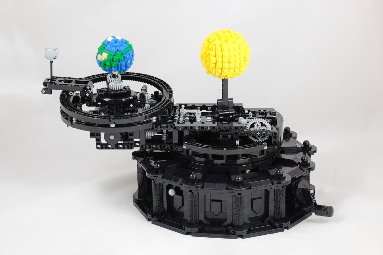
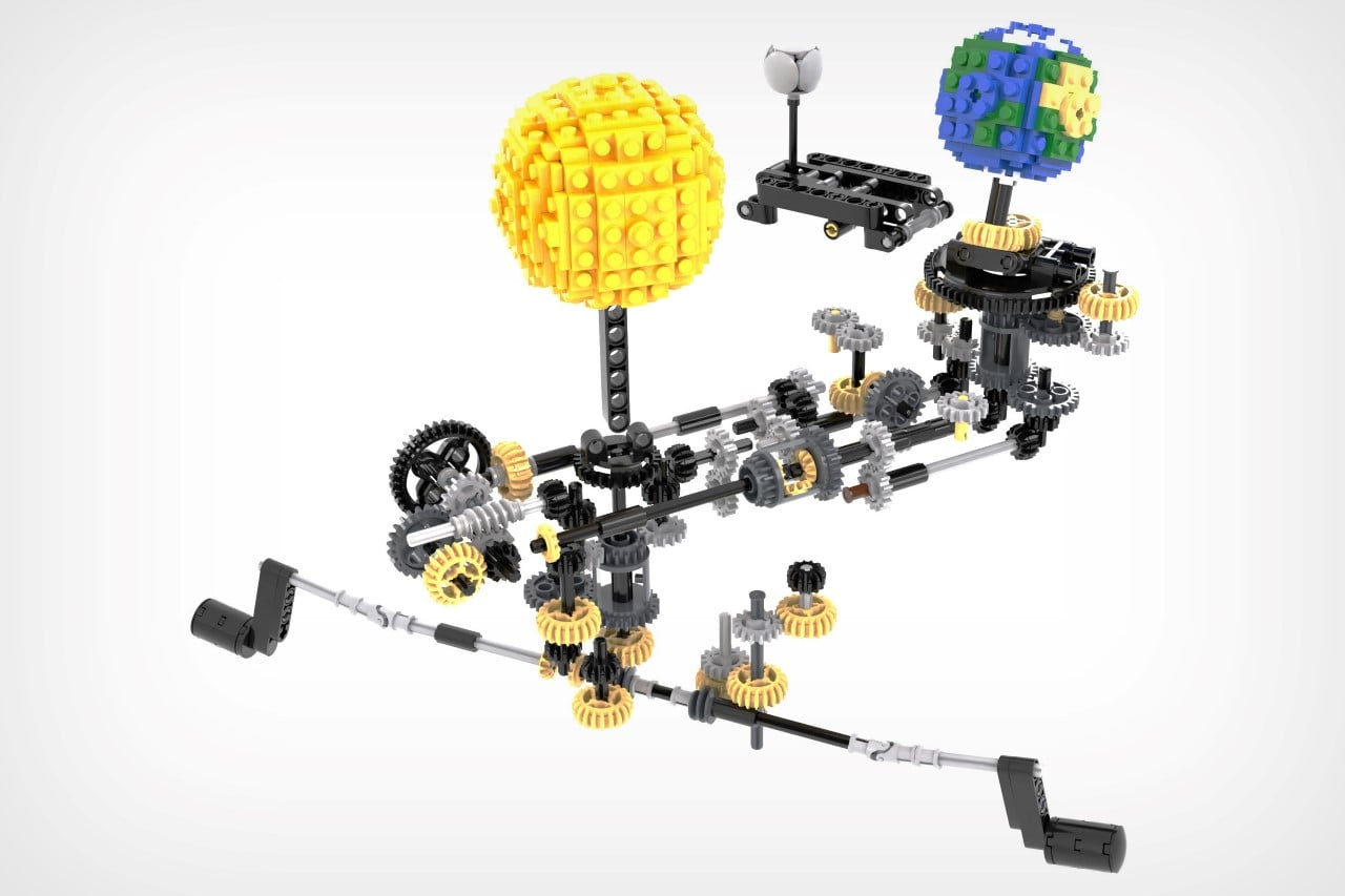
I’ll be honest, even after decades, LEGO still holds the potential to absolutely amaze me with its capabilities. The LEGO Sun Earth Moon Orrery is a stunningly detailed little kinetic machine that doesn’t just replicate the movement of the earth and moon around the sun, it also factors in the earth’s axial tilt, tracks moon phases, demonstrate solar and lunar eclipses, and aims at being as astronomically accurate as possible. Made from a staggering 2303 pieces, the Sun Earth Moon Orrery uses 70 Technic gears to allow the cosmic bodies to move realistically and can either be manually controlled using a hand crank or electrically via an RC motor.
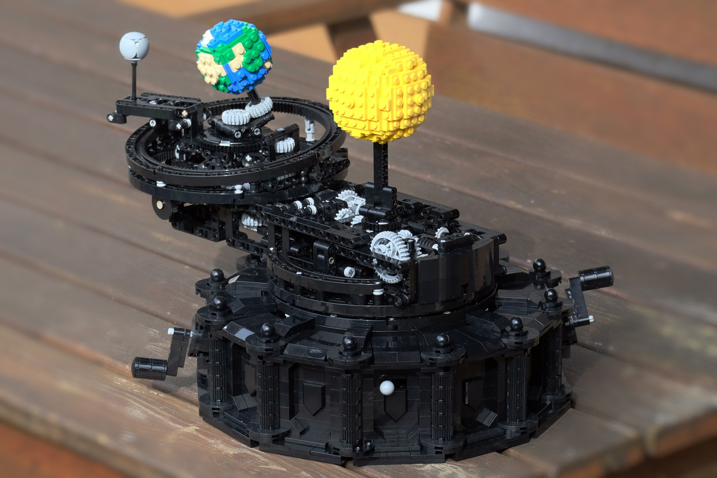
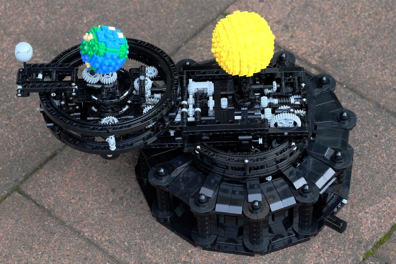
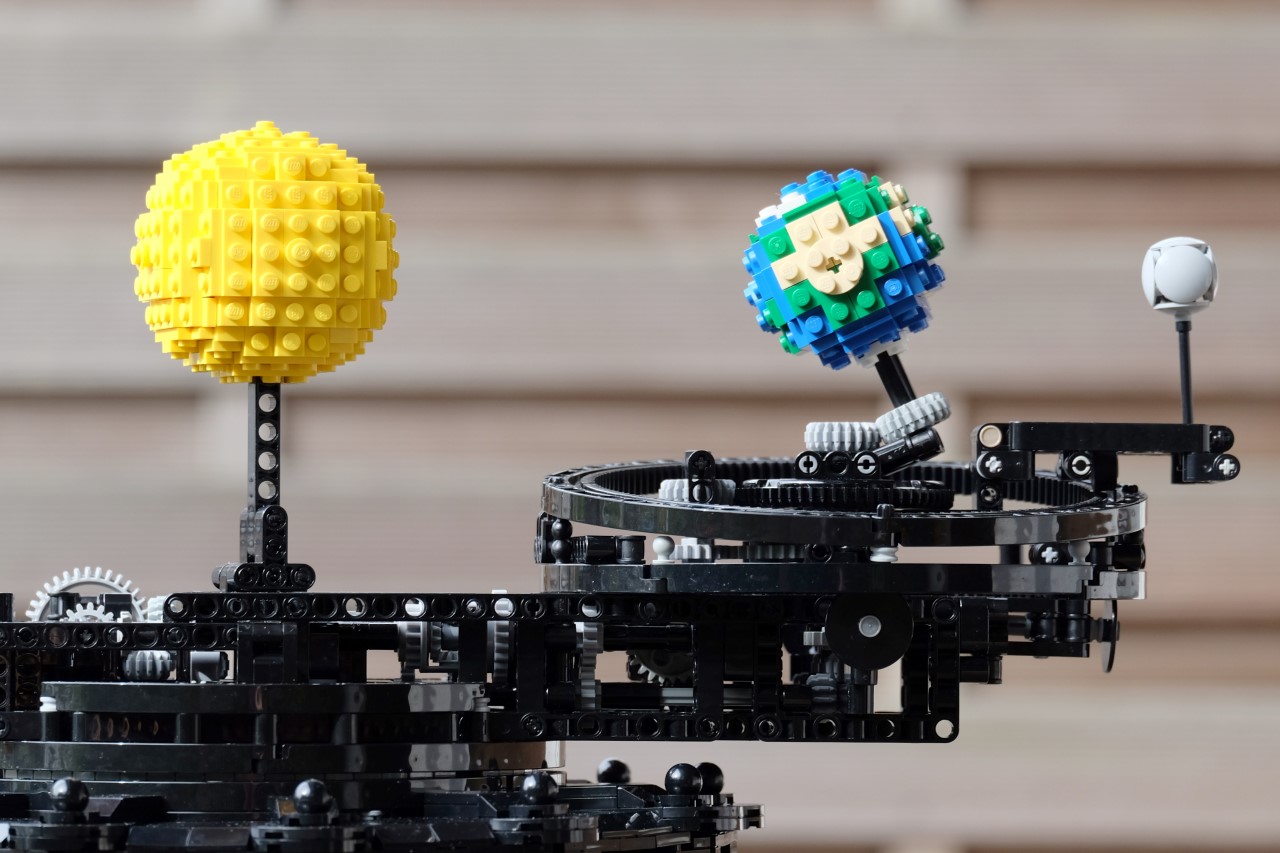
In true Da Vincian fashion, the LEGO Sun Earth Moon Orrery is as ornate as it’s intricate. Multitudes of well-placed gears allow the miniature earth to rotate on its tilted axis while revolving around the sun, while the moon does the same, completing one rotating and revolution around the earth with each spin. Designed and built by LEGO creator ‘Marian’, the Orrery measures 10.6 inches wide if you count just the 12-faced faceted base (to celebrate the 12 months of the year), and a stunning 20.9 inches if you also factor in the moving earth and moon.
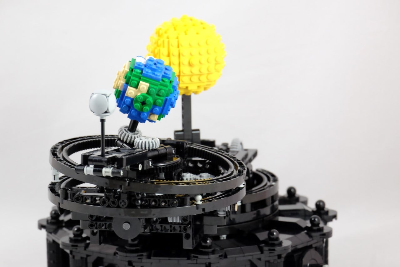
The kinetic orrery realistically models the rotational periods of the sun, earth, and moon along with the orbital periods of the latter two. The earth’s axial tilt lets you easily demonstrate concepts like seasons, solstices, and the change in the sun’s position based on which hemisphere you live on. It also helps accurately depict sunrises and moonrises, how solar and lunar eclipses work, moonphases, tidal locking, and even allows you to track solar and lunar calendars with stunning accuracy (especially for a LEGO kit).
While the LEGO Sun Earth Moon Orrery isn’t available as a standalone kit, you can buy it by checking out Marian’s inventory of parts on Rebrickable. Although do be warned, this fairly complex build comes with a 264-page instruction manual detailing the entire build process in an exhausting 436 steps!
Introduction: Make a Tellurion (sun-earth-moon Orrery) for Your Kid
A tellurion is a module for simulating the movement of earth and moon. This kind of module can be found in museum, but seldom seen in market. Some simplified version of tellurion can be found on internet, however a complete (almost) tellurion module was seldom made by DIYers. In this manual, I will explain how I designed (original) and made the tellurion using material bought from internet stores. The total cost without shipping fee is around $80, which includes gears, copper tubes, bearings, motor, LED, and 3D printed parts. To assemble the tellurion may need 5+ hours. All design use the free online 3D tool onshape.
Step 1: Introduction
My son Linxi likes knowledge about solar system a lot. I found a video series about solar system for kids on Youtube, and my son watched them all, again and again. One day, I found a video about wooden tellurion holzmechanik, which inspired me to make one for my son.
The design of the tellurion from holzmechanik is great: simple and elegant. However I don’t have tools to cut wooden gears as shown on the video. Besides, the earth doesn’t spin, which is a pity (I know to add this feature will need more gears, which will weaken the simplicity and elegant of the design)! However, a spinning earth can demonstrate how day and night shift. So, I think that feature must be kept.
The design of Solar System Orrery inspired me a lot. However, the sun in that design will spin, which not match with the truth. But the design of 3D sun with LED gave me new idea to make the sun of my tellurion model illuminate.
Watched more videos, I found that the orbit plane of moon is inclined to the ecliptic by about 5° , and that’s the reason why lunar eclipse occurs (shame! I don’t know that before). So this feature is also very important, must have.
So, my tellurion must have the following features:
- The earth will spin
- The moon rotate around earth with 5 degree inclination
- Sun is a light bulb.
- Axis of earth always point to Polaris.
With above feature, the tellurion can demonstrate day and night shift, seasons change, sun and moon eclipse and moon phases.
Step 2: Design & Materials
There are a lot orrery and tellurion models on **Youtube**, most of them were made in copper, which I don’t have tools to make myself. And I don’t have tools to make wooden gears neither, so I decided to make the tellurion using acrylic. I don’t have tools to cut acrylic neither, but there are many web stores selling this service.
The 3D design for gears and 3D printed parts are available. Note, when cut the gears using laser cutter, the width of the laser should be considered.
You can use other sizes of the tubes and bearings by modifying the design which I think is always necessary. Note: as "the_tool_man" mentioned, using bushings instead of ball bearings may solve the backlash problem, and I really hope you can have a try.
Attachments
Step 3: Mechanism
- Plate A & gear B belong to moon part, they are glued together, and spin around their axis (tube).
- Gear C & D are glued together and fixed to the axis. So they will not spin. When the support arm rotate with its axis, due to gear C is fixed, so gear B will start to rotate, so the plane A. This will simulate the rotation of moon to earth.
The left gear to the biggest gear is designed for moon. Moon has a period about 27.32, so moon will have 365.25/ 27.32 = 13.369 rounds a year. The ratio of diameters of the two gears should be 13.369. We can’t have exact ratio due to the number of gears’ teeth have to be integer. So I wrote a script (in R) to find the best gears:
Run above script we can get result:
So, the best gears are 134 & 10, however, the diameter is a little bigger (268 cm), so I choose the pair: 120 & 9.
- Gear D, E, F, G and H were designed to make sure that gear H will rotate one round a year, this will lead to the axis of earth always point to Polaris. The number of teeth of gear D&H and gear E&G should be equal respectively.
- Gear I, J, K, L, M, N, O & P were designed to increase gears speed, which targeted to the spin of earth. Gears N&O, gear L&M, gear J&K were glued together and can spin with their axis respectively. Gear I fixed to its axis, while its axis can spine inside the outer tube which finally lead to the spin of earth.
- Gear V, U, T, S, R & Q were designed as reduction gears, which will drive gear G, and finally drive earth rotate with sun. Gear S&R, gear U&T were glued together and spin with their axis respectively. Gear V is fixed to its axis. Gear G is fixed to its axis, so it can drive gear F and E to rotate. While gear D is fixed to its axis, so gear G will actually drive the support arm to rotate with its axis, which simulate the rotation of earth to sun.
- Gear P, Q & I together with plane 3 & 4 were glued together and can rotate with their axis.
- Gear X, Y are reduction gears, and gear Y will be drive by motor.
- Gear I - V were used to ensure that earth rotates 365 rounds a year. The mathematical relationship of the gear group is that when gear V rotate one round, gear I should rotate 365 rounds. To find the correct teeth numbers of gears, I wrote this script (in R):
I got two groups which are very close to 365.25. I choosed the second one, so I can say this tellurion has only half day mistake in one year. Another reason to choose the second gearset is they make earth spine slower than the first gearset.

Click on the image for a movie (14 MB, needs Flash)
My son Benjamin and I built this orrery on Thanksgiving weekend in 1994. It was featured in the May-June 1995 issue of Lego Mania magazine.
Orreries are mechanical models of (at least part of) the solar system, illustrating the motions of the planets. The first modern orrery was built around 1704 by George Graham. The device gets its name from Charles Boyle, who was the fourth Earl of Orrery and who commissioned the instrument maker John Rowley to make one from Graham's design for the Earl's son, John.
This orrery, made entirely of Lego, shows the Sun, Earth, and Moon. Originally it was powered by a classic 4.5V Lego motor, which was discontinued at about the time this model was created. A Lego 9V motor, also discontinued, is shown in these photos. The current Lego 9V motors have internal gearboxes that reduce the rotation speed and greatly increase the torque; it would be unnecessary to gear down one of these motors as much as has been done in this model.
We exhibited this orrery at Brickworld 2007, and for the occasion, my son Jeremy replaced its original Sun with the elegant one shown in the movie, based on Bram Lambrecht's Lowell sphere generator. The new Sun is nearly four times as massive as the original (visible in the Lego Mania article), which contributes to the wobble accompanying its rotation; replacing the current belt drive (the yellow band joining the pulleys near the top of the left-hand photo) with a chain drive might reduce the shimmy.
Sharp-eyed observers might notice a few other elements that have been replaced since the Lego Mania article was published; these changes are cosmetic rather than functional.
How it compares with the real thing
At Brickworld, one of the first questions many people asked was "Is it to scale?" Well . no. If everything else were made to the scale of the Sun, none of it would fit in the same room, and we wouldn't be able to see most of it. Space is pretty empty.
But the time scale is reasonably consistent:
| Solar System | Lego Orrery | |
| Earth rotation | 1 day | 1 scale day (~ 3-4 seconds, depending on the battery) |
| Earth revolution | 1 year (~365.24 days) | 360 scale days |
| Moon rotation | ~27.3 days | ~27.9 scale days |
| Moon revolution | same as rotation | same as rotation |
| Sun rotation | 24-30 days, depending on latitude | 27 scale days |
| Battery life | 10 billion years | 6-8 scale years (1.5-2 hours) |
How it works
There is a small pulley (a bushing) on the motor axle, that drives the large pulley to the left, and a worm gear (not visible in the photos) on the same axle as the large pulley. In the time scale of the model, one complete rotation of the large pulley is equivalent to one hour in the real solar system. Two separate gear trains are driven by this worm gear.
In the left-hand photo, a 24-tooth ("24t") gear is driven by the worm gear, and transmits its rotation via an axle that passes through the large grey 56t gear to the pair of 24t gears above the long yellow beams. Since the worm gear behaves like a one-tooth gear, the 24t gears turn once per "day" (24 revolutions of the worm gear). The 56t gear (actually, one piece of a large turntable) has a large center hole and is not driven by the axle that passes through it. One 24t gear is connected by a chain to the earth-moon gear train at the end of the long beam; the other 24t gear meshes with a 27:1 gear train (using three 24t/8t steps of 3:1 reduction) to drive the 27-day solar rotation. Note that there is a turntable between the two yellow cylinder bricks, so the pulley above the turntable turns at a slower rate than the gears below; the leftmost pulley is driven by the 24t gear on top, and is not connected to the one below.
The second gear train driven by the worm gear is to its right, and is visible in the center photo. Again, the worm drives a 24t gear to turn once per day, and then a 360:1 reduction follows: 24t/8t (3:1), 24t/8t (3:1), 40t/8t (5:1), 16t/8t (2:1), a follower to reverse direction (24t/24t), and finally the 56t wheel is chain-driven by a 14t gear (4:1). Since the long beam that bears the Earth and Moon is attached to the 54t wheel, the model Earth makes one complete orbit of the Sun in 360 "days", not exactly a year, but fairly close!
At the end of the long beam (see the right-hand photo) the 24t gear, driven by the chain, turns once per "day", as does the Earth, driven by the 1:1 belt drive beneath the long beam. The large white pulley on the Earth's axle/axis (above the beam) is actually a wheel hub with a round center hole, and it is not driven by the axle; rather, it rotates approximately once per 27.3 "days" (via two 24t/8t steps of 3:1 reduction, and a final reduction of about 3.1:1 in the belt drive from the small pulley to the wheel hub. The Moon, at the end of the black arm attached to the wheel hub, thus orbits the Earth in about 27.3 days. Note that the Moon's orbital period is shorter than the interval from (for example) full moon to full moon (one lunar month, or 29.5 days), because the Earth's motion around the Sun requires the Moon to travel more than a full orbit before returning to the same phase. (Naturally this feature is also exhibited by the orrery.)
Components
The entire orrery is constructed from unmodified Lego components, without glue or lubricants. Most are common Lego Technic elements.
None of the components are really unusual, although it should be noted that the 2x6 red bricks on the short end of the beam are Lego weighted bricks (which were formerly available in a package of 4, set number 9863, and have also been included in many Lego Dacta sets). These bricks enclose a metal slug; they weigh 50g each, and are useful for balancing crane arms, bridge spans, and small planets (as in this model). The 56t gear, as noted, is the upper half of a Lego Technic large turntable, which can be separated from the lower half without damaging either element. The various belts are also Lego elements; the originals were all black rubber (which is less durable than the blue and yellow neoprene replacements in the photos).
We built the Earth at a time when green bricks were unavailable (although it includes a few transparent green plates and bricks). We have occasionally thought of making a rounder Earth, but (just as in the real solar system) we have only one Earth and it seems worthwhile to take care of the one we have, bumps and all. The chain links, which look and work like micro-scale bicycle chain links, have been available on and off for many years; they are currently included in the Technic motorcycle (an expensive way to acquire them!) and are available in bulk packs as well.
Don't miss .
There are other Lego orreries on the web. See Don Rogerson's site for an especially accurate one, and for links to several more.
Читайте также: