
Lego power functions servo motor
Обновлено: 02.05.2024
Learn how to control Lego motors and servos with your Arduino and build your own Android app to remote control your model.
- 94,690 views
- 6 comments
- 92 respects
Components and supplies
About this project
Do you have one of those awesome Lego Power Functions models with electrical motors and servo-motors? In this tutorial I will show you how you can control your Lego model with your Arduino and a minimum of electronic components. I will explain the circuits and programming in detail to make this tutorial easy understandable for beginners. The Lego model you will have to build yourself (if you don't have a son), I won't help you with that.
We will also learn how to use the MIT app inventor to program our own remote control Android app. Soon, you will have your own Lego Mars rover in your backyard!
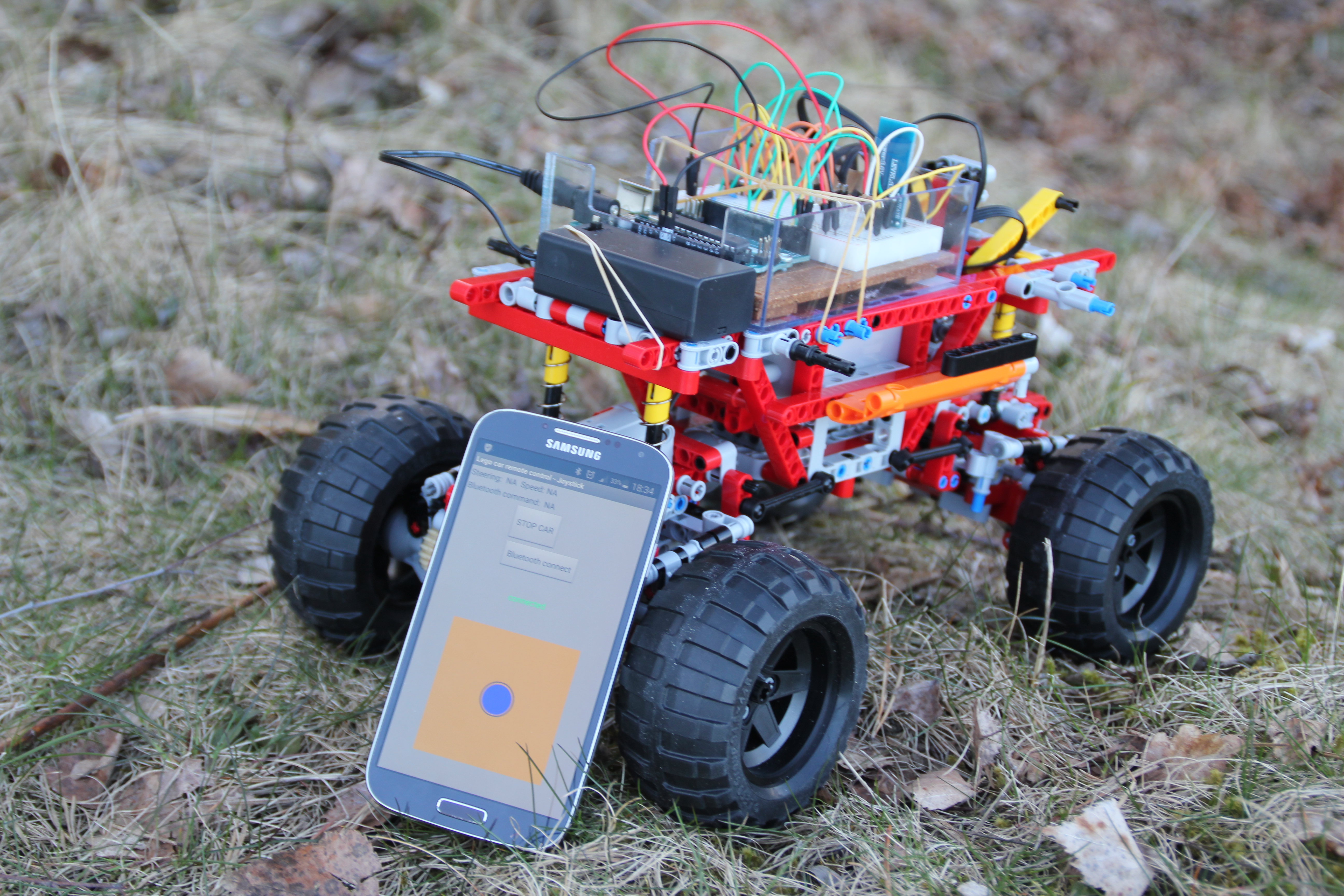
This is my first Arduino project and my son has a beautiful Lego Technic car model ( 9398 4X4 Crawler ) with Lego Power Functions: one Lego Servo Motor for steering and two Lego L-motors for driving. He allowed me to use the car for this project (as long as I didn't cut up any motor cables). Here, we test the finished prototype:
Understanding the Power Functions wiring
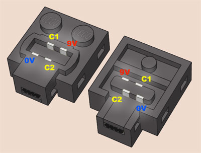
First, buy some Lego Power Functions Extension wires (item 8886 in the Lego web shop). Next, cut them up (seriously). We will make some "break-out"-cables that have Lego bricks at one end and pins at the other end. Solder the pins on or similar. Here is the wiring explained:

Female Lego plug (pin layout)
GND stands for Ground which is the negative terminal (-) of the battery pack (anode). C1 and C2 can switch polarity to make the motors and servos switch direction. TechnicRobot has made a nice video explaining everything in detail. (WARNING: you are doing this on your own responsibility. I will not be held responsible if you ruin something!) For the Lego servo connector, you need to solder on pins to all four cables. You can use the light grey plug. For the power cable connecting the battery box with the breadboard, we need only +9 Volt and GND but you have to use the dark grey plug (because you need a male connector):

battery box plug
For the motor cable, we need only to connect C1 and C2 and you can use a light grey plug. (Study the schematics for details).
Controlling a Lego motor with the L293D chip
We want variable speed control for our DC motors and position control for our Lego servo. This is achieved by Pulse Width Modulation (PWM) . The Arduino's programming language makes PWM easy to use; simply call analogWrite(pin, dutyCycle) , where dutyCycle is a value from 0 to 255. The PWM pins are marked with ~ on your arduino.
The Arduino output pins are 5 Volt and max. 30 mA while the Lego motors need 9 Volt and pull more than 100 mA each. We need some kind of "switching device" in-between. We also want to be able to run the DC motors in both directions. These functions are solved by a so-called H-bridge . We will use the L293D , which contains two H-bridges on one integrated chip, which means we can connect the Lego motors (M) in parallel to one side and the Lego servo (S) to the other side of the chip. (If you want to control the two motors independently you will need a second L293D). The Lego servo also needs to be connected to GND and Lego +9 Volt.
The chip keeps Lego +9 Volt and Arduino +5 Volt completely separated. Never connect them together or you will damage something! But you have to connect all ground lines together and with the L293D ground pins.
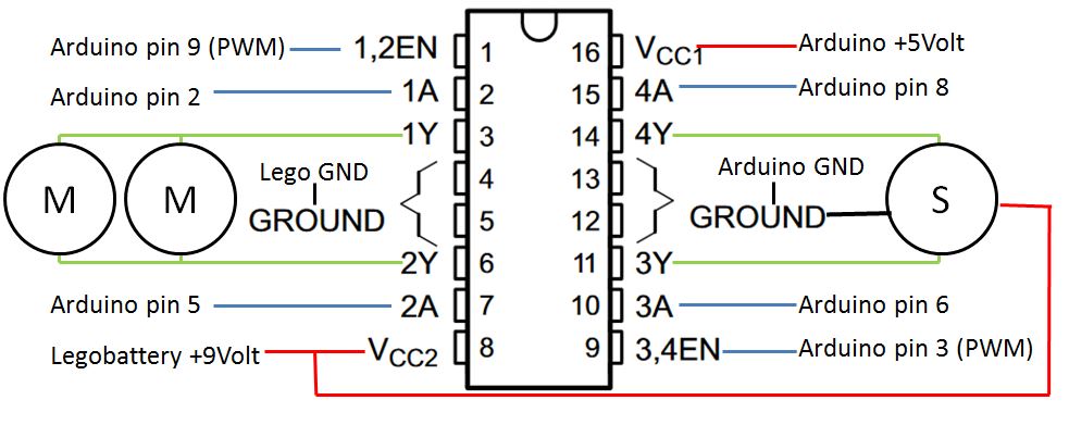
L293D pin arrangement (top view)
From our Arduino, we will use pin 9 to control the motor speed and pins 2 and 5 to control the rotation direction. The Lego servo is controlled like a motor: we connect pin 3 for position and pins 6 and 8 for direction (left or right).
At the top of our program, we define the used Arduino pins as constants. Further, we define some variables that we will use to control the motors:
In the setup, we define these pins as outputs with the pinmode() command and then set them to 0 Volt with digitalWrite() .
Now we need to understand how the L293D chip controls the rotation direction of the motors. We have to supply the following signals (High == 5 Volt; Low == 0 Volt):
- EN1,2 1A 2A
- High High Low Motor turns left (Forward; motorDirection == 1)
- High Low High Motor turns right (Reverse; motorDirection == 0)
- EN3,4 3A 4A
- High High Low Servo turns left (steeringDirection == 0)
- High Low High Servo turns right (steeringDirection == 1)
Ok. We are ready to write a subroutine that reads the global variables for direction and speed/position and controls the motors and servo:
Simple RC Android app with joystick
Next, let's build a simple Android app to control the model. (If you want to test the finished app first: I have made it available for you in the Google play store. Here is the link: Arduino RC car bluetooth ).
We will use the MIT app inventor 2 . MIT App Inventor is an innovative beginner's introduction to programming and app creation. Google's Mark Friedman and MIT Professor Hal Abelson co-led the development of App Inventor. It runs as a web service administered by staff at MIT’s Center for Mobile Learning.
On your Android phone, go to Google Play and install the MIT AI2 Companion app . On your computer, open the link to my RC app in either Firefox- or Chrome-browser (Internet Explorer not supported). You will have to log in using your gmail-address and create an account in order to see the source code. If you open the companion app on your phone, you can look at the source code in the browser, make changes to it and test it immediately on your phone.
In the browser, you will now see the Designer-view of the app:

Designer view in MIT App Inventor 2
At the bottom, we see the orange pad with the blue joystickball in it. Now change into the Blocks-view to see the program. The heart of the program is a when-block that keeps track of the movements of your finger touching and dragging the blue joystickball:
Blocks-view of the program
The position of your finger is tracked in the two variables currentX and currentY and is used to calculate values for the two variables steering and speed (range: -100..0..+100). First the program checks if your finger is outside the pad and limits the values to +/- 100. If the finger is inside the pad, the program calculates values for steering and speed . Next, the program generates a command-string of the form:
The command starts with "RC" for remote control (the idea is that in the future, you might want to have more commands) followed by a comma. Then we send the values for steering and speed . The newline-character ('\n') at the end of the command is a signal to the Arduino that the command is complete. This command-string is sent over bluetooth to the Arduino. For your reference, the string is also displayed on the screen.
Reading bluetooth-commands into the Arduino
In order to read the Bluetooth command strings, we need to connect a HC-05 Bluetooth module. Have a look at your module:
HC-05 Bluetooth module
Mine has 6 pins. We only need four pins. VCC is (positive) supply voltage and GND is ground. The module tolerates 6 Volt supply voltage, which means we can connect it to the arduino 5 Volt power pin. TXD and RXD are the serial signals. We have to cross the lines and connect TXD to arduino RXD (pin 0) and vice versa. Be careful: It states LEVEL: 3.3V which means that the RXD cannot be directly connected to the 5V arduino TXD (pin 1). We have to construct a voltage divider with three 1 kOhm resistors to produce an output voltage which is 2/3 of 5V (see schematics). On the other hand, the TXD signal of 3.3V can be directly connected to Arduino RXD. The Arduino will recognise 3.3 Volt as HIGH.
As pin 0 and 1 are shared with the USB port of your Arduino, you will have to disconnect the RXD and TXD signals from pin 0 and 1 while uploading the program over USB to the board. The upload won't work if you don't disconnect the cables.
Next, you have to pair the HC-05 module with your Android device. Switch Bluetooth on; start the app; press "Bluetooth connect"; make your phone visible and look for a device called HC-05 or similar. Select the device. You will be asked for a code. Press "1234". When you return to the joystick-screen, it should state "connected" in green.
Now, lets look at the code:
The string sent by the Android app is read into a special string-construct: a C-string with null-termination . (The 0-character tells the program that it has come to the end of the string). This is done by using the function Serial.readBytesUntil('\n', input, . ) , which reads from the serial interface (bluetooth) until it gets a newline-character ('\n'). That way, we keep reading bytes until we have a complete command in input :
A very efficient way to process input is the string token function, which cuts the string into parts using comma as a delimiter. The first call to strtok() returns "RC". The subsequent parts of the command are then read by passing NULL to strtok(). The returning values are stored in RCsteering and RCspeed . These variables are actually pointers to positions in input . The function atoi() converts them finally into integers. Now, we have:
We are almost done now. We have to multiply these values by 2.55 before we pass them on to our routine SetMotorControl() (Remember that motorspeed was in the range 0..255). Study the rest of the program in the CODE section, build the circuit and test your remote controlled Lego model!
Now that you have an Arduino controlling your Lego model, you might want to use that model as a robotics platform: add some ultrasonic ping sensors, program your own obstacle-avoiding logic and make your own self-driving robotic Mars rover. Or add more commands to the remote control and more functions to the model. But first, find a method for the Arduino to figure out that the model has traveled out of range of the bluetooth connection and stop the model. Tell me about your solution.
Soon enough, you will find out that a prototyping breadboard and loose cables are not a good idea for a moving model. Get yourself an adafruit motorshield with big terminal block connectors and rewire and reprogram. This will also free up digital signals that you can use for inputs instead. You might also consider a sensor shield for better connection of your sensors.
С появлением в 2007 году электрической системы LEGO Power Functions открылись новые интересные возможности для конструкторов, в частности моделей LEGO Technic:
- Моторизация
- Освещение
- Дистанционное управление
Наиболее важным и сложным на мой взгляд всегда является вопрос моторизации.

Ввиду множества существующих моторов, всегда возникает вопрос: какой мотор выбрать для той или иной функции модели? Но недостаточно правильно выбрать мотор - не менее важно правильно его применить, а именно:
- определить необходимую скорость и крутящий момент вала в конечном месте приложения усилия (вращение колес/рулевая система/поворот башни или подъем стрелы крана и т.д.)
- правильно выбрать место расположения моторов в модели
- надежно закрепить моторы
- грамотно построить трансмиссию
Под трансмиссией понимается совокупность закрепленных шестерней осей и прочих элементов для передачи крутящего момента от мотора к конечной точке моторизации. Более подробно я расскажу об этом отдельно. Отмечу лишь, что при неправильном планировании трансмиссии у модели будет низкий КПД и будут подвержены избыточной нагрузке отдельные элементы, что в конечном счете может привести к усиленному износу и даже поломке деталей трансмиссии.
На сегодняшний день линейка LEGO PF моторов представлена 4-мя моторами: L, M, XL, Servo. Дополнительно я включил в обзор скоростной 9V Race Buggy мотор, который не имеет аналогов в системе PF 2007 года. К сожалению, он уже не производится и не применяется в современных наборах, однако его можно купить б/у в достаточно хорошем состоянии.
8883 M (Medium) Motor. Средний мотор

- Мощность - 1,15 ватт
- Крутящий момент при частичной* нагрузке - 5,5 N.cm
- Максимальное потребление тока - 0,85 A
- Минимальное потребление тока (без нагрузки) - 0,065 А
* - нагрузка при которой обороты падают в два раза от максимума.
- Вес- 31 г.
- Провод - четырех-жильный, 20 см
- Размеры - 3x3x6.
- Интерфейс - Lego Technic, Lego System
- Система: Power functions (PF)
Мотор с невысокой мощностью. Широко распространен в наборах LEGO Technic.
Рекомендую использовать для рулевых систем, лебедок, пневмокомпрессоров, моторизации актуаторов, а также различных переключателей: коробок передач, пневмоклапанов и т.д. Применение возможно практически везде, где не требуется высокая мощность (высокая скорость и высокий крутящий момент одновременно).Поэтому для движения моделей данный мотор подходит плохо ввиду маленькой мощности.
Тем не менее, его можно использовать для движения моделей в следующих случаях:
- небольшие легкие модели;
- с понижающей передачей. Крутящий момент тем самым повысится, однако сильно снизится скорость;
- модели с несколькими М моторами для движения, например, по мотору на ось для полного привода или два мотора на ось - задний привод. Можно больше моторов, однако не целесообразно, так как проще установить более мощный мотор (L, XL) сэкономив при этом вес и свободное место.
Отличительной особенностью данного мотора является возможность его крепления к System элементам за счет площадки размером 2x6 снизу.
При использовании в рулевой системе почти всегда необходимо делать понижающий редуктор для большего усилия и точного поворота колес. В своих моделях с небольшой скоростью движения я использую понижение как минимум 8:24 + 12:20. При этом использую белую clutch gear 24 шестерню с проскальзыванием для защиты рулевой от поломки в крайних. Также мотор хорошо подходит для рулевых систем с автовозвратом (возврат колес в центральное положение) с использованием резинок или других конструкций. В этом случае понижающий редуктор не требуется.
Мотор хорошо подходит для прямого подключения к линейным актуаторам практически для всех случаев применения.
К IR ресиверу можно подключать до 4-х M моторов, к одному выходу ресивера до 2-х моторов. ВНИМАНИЕ: для использования 2-х моторов от одного выхода IR ресивера необходимо использовать ресивер старой версии НЕ v2 !
88003 L (Large) Motor. Большой мотор

- Мощность - 2,14 ватт
- Скорость вращения без нагрузки - 390 об/мин
- Крутящий момент при частичной* нагрузке - 10,5 N.cm
- Максимальное потребление тока - 1,3 A
- Минимальное потребление тока (без нагрузки) - 0,12 А
* - нагрузка при которой обороты падают в два раза от максимума.
- Вес- 42 г.
- Размеры - 3x4x7
- Интерфейс - Lego Technic
- Система: Power functions (PF)
Большой мотор впервые появился в наборе 9398. Мотор универсален: обладает высокой скоростью вращения (почти как у М мотора) и достаточным крутящим моментом для движения модели. Преимущество использования данного мотора в качестве движущего - быстрый, легкий, компактный и не "рвет" трансмиссию (как XL). Может использоваться на скоростных машинах, моделях с моно/полным приводом и триальных моделях (не менее 2х моторов). При понижении редуктором итоговый крутящий момент в месте приложения будет немногим меньше чем от XL мотора при равной скорости. Рекомендую для наибольшей мощности использовать по два мотора одновременно - размеры мотора в большистве случае это допускают (в отличие от громоздкого и неудобного XL)
L Мотор может использоваться везде, где мощности М мотора недостаточно - в рулевых системах, строительной технике и т.д.
Из прочих преимуществ мотора - наличие множества крепежных отверстий.
В ближайшее время мотор будет активно использоваться компанией LEGO в новых техник наборах, замещая M мотор (например, набор 2013 года - 42009 Mobile Crane Mk II)
Недостаток, на мой взгляд один: несмотря на заявленную ширину 4 дырки, на практике он занимает в конструкции все 5 дырок, что не всегда удобно.
8882 XL (Extra large) Motor. Экстра-большой мотор

- Мощность - 2,65 ватт
- Скорость вращения без нагрузки - 220 об/мин
- Крутящий момент при частичной* нагрузке - 23 N.cm
- Максимальное потребление тока - 1,8 A
- Минимальное потребление тока (без нагрузки) - 0,08 А
* - нагрузка при которой обороты падают в два раза от максимума.
- Вес- 69 г.
- Размеры - 5x5x6
- Интерфейс - Lego Technic
- Система: Power functions (PF)
Мотор с высокой мощностью. У него невысокая скорость вращения вала, при этом огромный крутящий момент. Отлично подходит для полноприводных внедорожников, грузовиков и триальных машин с меделнной скоростью передвижения и потребностью в большом крутящем моменте.
Оффициально мотор применялся в трех наборах: 8275, 4958 и 8258. Возможно, отказ от его дальнейшего применения в официальных наборах - отзывы потребителей о сломаных деталях. Это мое предположение. Надеюсь, мы еще увидим его в действии. В противном случае, мотор в ближайшем будущем рискует стать дорогим раритетом как 9V Race Buggy мотор.
ВНИМАНИЕ : В руках неопытного строителя мотор часто приводит к сломанным шестерням, карданам и скрученным осям! При постройке модели необходим делать особо прочную трансмиссию для передачи высокого крутящего момента от мотора к колесам. Желательно ставить мотор максимально близко к оси исключая множество осей и передач, тем самым исключая риски поломок и повышая надежность в экстремальных нагрузках.
Постройка скоростных моделей с данным мотором затруднительна и неэффективна ввиду невысокой скорости вращения вала. Повышение скорости вращения за счет повышающего редуктора приводит к потерям крутящего момента.
Кроме движения моделей (8275 и 4958), мотор также подходит для второстепенных функций - там где нужна высокая мощность (как в 8258), или где нет возможности поставить М мотор с понижающим редуктором.
Недостатками данного мотора являются его большие размеры и вес.
В машинах среднего размера используют 1 мотор. В тяжелых и мощных моделях - 2 и больше.
9V Race Buggy Motor. Багги мотор.

- Мощность - 4,96 ватт
- Скорость вращения без нагрузки:
- внешний выход - 1240 об/мин
- внутренний выход - 1700 об/мин
- Крутящий момент при частичной* нагрузке:
- внешний выход - 7,7 N.cm
- внутренний выход - 5,69 N.cm
- Максимальное потребление тока - 3,2 A
- Минимальное потребление тока (без нагрузки) - 0,16 А
* - нагрузка при которой обороты падают в два раза от максимума.
- Вес- 55 г.
- Размеры - 5x5x10
- Интерфейс - Lego Technic
- Система: 9V
Самый мощный лего-мотор. В настоящий момент не выпускается. Высокая скорость вращения вала, при этом достаточный крутящий момент. Отлично подходит для легких и средних скоростных машин. При использовании редуктора можно использовать в триальных моделях.
Мотор использвался в линейке наборов Racers (8475, 8366, 8376), Technic (8421, 8287) в 2002-2006г.в. Сейчас не выпускается. Можно найти "бу" в хорошем состоянии.
Имеет два сквозных выхода с разной скоростью вращения.
ВНИМАНИЕ: мотор необходимо использовать с PF IR приемниками версии 2 (v2, от набора 9398) так как приемники старых версий не дают мотору выйти на полную мощность и при малейшей нагрузке на вал включают защиту от перегрузки. Кроме того мотор можно использовать с блоком радио-управления (уже не выпускается) от набора 8475, который рассчитан на работу с двумя моторами одновременно.
ВНИМАНИЕ: Для подключения к системе Power functions, ввиду разных коннекторов, необходим переходник-удлинитель 9V-PF 20 см (продается отдельно).
Данный мотор мощнее чем XL. В триальных моделях, мотор позволяет ехать с более высокой скоростью. Легким скоростным моделям мотор позволяет достигать высоких скоростей (до 10 км/ч). Кроме того, возможна постройка легких дрифт-моделей.
Ввиду высокого потребления, к одному v2 IR приемнику можно подключить 1 багги мотор (+ маломощный м- или серво- мотор для руления, при необходимости). Кроме того для каждого багги мотора крайне желательно иметь отдельный батарейный блок.
Преимущества: высочайшая мощность и возможность использования в любых моделях.
Недостатками данного мотора являются его большие размеры и крайне неудобное крепление из за Г- образной формы мотора. Мотор потребляет много энергии.
- Размеры мотора - 3х5х7. Имеется множество отверстий для крепления.
- Интерфейс - Lego Technic
- Система: Power functions (PF)
- Скорость вращения мотора без нагрузки - 90 градусов за 0,25 сек, то есть колеса поворачиваются из центрального в крайнее положение за 0,25 сек. На практике скорость вращения сильно зависит от нагрузки.
Этот долгожданный мотор появился впервые в наборе 9398. Мотор сделан для одной цели - поворот управляемых колес как на настоящих машинах. Он не совсем похож на традиционные сервомоторы радиоупраыляемых моделей, однако в нем реализованы функции автовозврата и поворота колес на разные углы.
Вал мотора не вращается бесконечно, как на обычных моторах: он поворачивает на 90 градусов по часовой стрелке и на 90 градусов против часовой. Итого - 180 градусов. При этом, при опускании рычага управления стандартного пульта (или нажатии на кнопку сброс/стоп пульта с плавной регулировкой) мотор возвращает вал в центральное положение (то есть колеса авто встают прямо). Помимо этого мотор позволяет устанавливать 7 различных углов поворота колес в каждую сторону: всего 14 позиций + центральная. Для этого необходим пульт с плавной регулировкой, как в наборах с поездами.
Мотор имеет передний и задний выходы соединенные вместе. Это позволяет легко реализовать поворот одновремнно передней и задней осей.
Если мотор управляется обычным пультом с рычагами: при нажатии на рычаг мотор поворачивается на максимальный угол - 90 градусов.
При управлении мотором пультом с регулировкой скорости мотор будет поворачивать вал постепенно в соответствии с вращением колеса пульта.
ВАЖНО: при строительстве модели вал мотора должен быть выровнен по центру - 4 точки на моторе и оранжевом выходе вала должны лежать на одной линии. Для центровки нужно подключить мотор к любому выходу IR ресивера подключенного к включенному батарейному блоку. В этом случае вы услышите кратковременный звук мотора - центровка произведена. Пульт при центровке трогать не нужно!
Мотор не очень подходит для очень скоростных машин (как правило, они на багги моторах) ввиду относительно медленной скорости поворота вала. Пожалуй, это единственный недостаток. Пусть он вас не смущает - построить очень быструю машину не так то просто. Если вы новичок - сервомотор значительно облегчит вам постройку модели. Модель с таким мотором легче управляется ввиду наличия автоцентровки колес, что очень важно если играть моделью будет ребенок.
В заключение хочу представить вам наглядные сравнительные характеристики от Sariel. Скорость моторов указана "средняя рабочая", а не максимальная. Тем не менее вы можете сравнить и соотнести характеристики моторов между собой.

LEGO ® Power Functions Servomotor
This Power Functions element appeared first in 2012 Rock Crawler set (9398), used for steering. Like RC servos, its output turns within a limited range (-90° to +90°) in response to a control signal. Being a Power Functions range member, it is fully integrated with this system, and receives its commended position through C1/C2 lines, and its power from supply lines. On a normal motor, C1/C2 duty cycle directly control motor speed, here they set the angular position of the shaft.
This article details the behavior of the PF servomotor and how well it performs.
The setup is similar to the one I use to compare motors. The servo is powered by a laboratory power supply, through a Mindsensors PowerMeter sensor used to measure current. A Hitechnic Angle sensor monitors shaft angle. Weight lifting provides the load - with a little drawback, the load is always applied in the same direction. C1/C2 lines of the servo are directly connected to measuring NXT port B, allowing a full control of the servo by varying "power level" (actually, PWM duty cycle) on this port. Here is a sample of the NXC programs that I used during the tests.
Proportional?
One of the first question that was asked when the servo appeared was: "does it provides proportional action, or only right/center/left positioning"? efferman soon posted a video showing a proportional control when using PF speed controller. But this device only generate discrete speed steps - what happens between steps?
My setup using NXT to control C1/C2 lines allows to set any PWM duty cycle between -100% and +100%. and as shown in the video below, the PF servo has only seven positions on each side of neutral.
Servomotor behavior
- we start at full CCW position (PWM set at full forward, servo mechanical stop, load weight is at lower position). Angle is about 0°
- at t=2s, we send to the servo the order to go to full CW position (PWM set at full reverse, load weight is lifted at upper position). Angle is about 180°
- at t=4s, we send to the servo the order to go to neutral position (PWM set at 0°)
- at t=6s, we go again to full CCW position.
- at t=8s, return to neutral.
We see from these charts that - as expected - power consumed by servomotor increases with torque applied. Spikes of current at 8.5N.cm load reaches 600mA.While the servo soon reaches a position close to the target, it struggles more and more to reach it as load is increased.
Shaft angle curves under various loads
On this chart, I have plotted the three shaft angle curves under various loads. We see that there is a small dead time between the order and the rotation start (about 0.12s). It then takes about 0.12s to rotate 90°. The total reaction time is thus about 0.25s for a 90° angle change, 0.36s for a full 180°. There is little speed change with increased load to reach a good approximation of target angle, the final settling time does increase significantly. We can see also that the final angle depends on the load. I don't know if this is caused by poor regulation, play in internal gearing of the servo, or elasticity in my own test bench.
If we continue to increase load on the servo shaft, new things happen, as shown on the curves below. Blue curve is current consumed, red curve is angle variation at no load, drawn as reference. Pink curve show shaft angle at full load.
12.8 N.cm, 9V supply.
Reaching target angle is now much longer, about 1.7 seconds to go from -90° to +90°. But the real difference is that the servo doesn't hold on the target angle! As soon as target angle is reached, we see that the load drives the shaft back to -90° position. This means that once the servo has reached its target, it doesn't try to correct and maintain its position anymore, as a regular RC servo would do. And most probably, it doesn't even brake the motor by shorting it (or only briefly). The load can thus relatively easily back drive the servo, once the internal friction is overcome.
12.8 N.cm, 7.2V supply.
The above chart shows the same heavy load test, this time performed with a 7.2V power supply (the nominal voltage of 6 AA NiMH cells). We see that even at this low voltage the servomotor is quite powerful (only the ramp-up is slower), and of course we see the same back drive by the load.
An other way of overloading the servomotor is to block its normal travel.
+/- 45° blocked travel
In the above chart, I put two stops on each side of the servo travel, limiting it to +/-45°. We see that after a short normal move to reach 45° (at low current since there is no external load), the servo motor hits the stop. There the current is increased to the maximum (900mA) for a short time (less than 0.25s), then the servo stops trying, and stays idle till it receives an other order. This means that no harm will be done is the servo is accidentally blocked in its travel - of course I don't recommend this as normal practice!
Learn how to control Lego motors and servos with your Arduino and build your own Android app to remote control your model.
Things used in this project
Hardware components
Story
Do you have one of those awesome Lego Power Functions models with electrical motors and servo-motors? In this tutorial I will show you how you can control your Lego model with your Arduino and a minimum of electronic components. I will explain the circuits and programming in detail to make this tutorial easy understandable for beginners. The Lego model you will have to build yourself (if you don't have a son), I won't help you with that.
We will also learn how to use the MIT app inventor to program our own remote control Android app. Soon, you will have your own Lego Mars rover in your backyard!
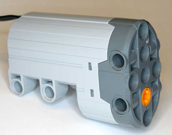
This is my first Arduino project and my son has a beautiful Lego Technic car model ( 9398 4X4 Crawler ) with Lego Power Functions: one Lego Servo Motor for steering and two Lego L-motors for driving. He allowed me to use the car for this project (as long as I didn't cut up any motor cables). Here, we test the finished prototype:
Understanding the Power Functions wiring
First, buy some Lego Power Functions Extension wires (item 8886 in the Lego web shop). Next, cut them up (seriously). We will make some "break-out"-cables that have Lego bricks at one end and pins at the other end. Solder the pins on or similar. Here is the wiring explained:
GND stands for Ground which is the negative terminal (-) of the battery pack (anode). C1 and C2 can switch polarity to make the motors and servos switch direction. TechnicRobot has made a nice video explaining everything in detail. (WARNING: you are doing this on your own responsibility. I will not be held responsible if you ruin something!) For the Lego servo connector, you need to solder on pins to all four cables. You can use the light grey plug. For the power cable connecting the battery box with the breadboard, we need only +9 Volt and GND but you have to use the dark grey plug (because you need a male connector):
For the motor cable, we need only to connect C1 and C2 and you can use a light grey plug. (Study the schematics for details).
Controlling a Lego motor with the L293D chip
We want variable speed control for our DC motors and position control for our Lego servo. This is achieved by Pulse Width Modulation (PWM) . The Arduino's programming language makes PWM easy to use; simply call analogWrite(pin, dutyCycle) , where dutyCycle is a value from 0 to 255. The PWM pins are marked with ~ on your arduino.
The Arduino output pins are 5 Volt and max. 30 mA while the Lego motors need 9 Volt and pull more than 100 mA each. We need some kind of "switching device" in-between. We also want to be able to run the DC motors in both directions. These functions are solved by a so-called H-bridge . We will use the L293D , which contains two H-bridges on one integrated chip, which means we can connect the Lego motors (M) in parallel to one side and the Lego servo (S) to the other side of the chip. (If you want to control the two motors independently you will need a second L293D). The Lego servo also needs to be connected to GND and Lego +9 Volt.
The chip keeps Lego +9 Volt and Arduino +5 Volt completely separated. Never connect them together or you will damage something! But you have to connect all ground lines together and with the L293D ground pins.
From our Arduino, we will use pin 9 to control the motor speed and pins 2 and 5 to control the rotation direction. The Lego servo is controlled like a motor: we connect pin 3 for position and pins 6 and 8 for direction (left or right).
At the top of our program, we define the used Arduino pins as constants. Further, we define some variables that we will use to control the motors:
In the setup, we define these pins as outputs with the pinmode() command and then set them to 0 Volt with digitalWrite() .
Now we need to understand how the L293D chip controls the rotation direction of the motors. We have to supply the following signals (High == 5 Volt; Low == 0 Volt):
- EN1,2 1A 2A
- High High Low Motor turns left (Forward; motorDirection == 1)
- High Low High Motor turns right (Reverse; motorDirection == 0)
- EN3,4 3A 4A
- High High Low Servo turns left (steeringDirection == 0)
- High Low High Servo turns right (steeringDirection == 1)
Ok. We are ready to write a subroutine that reads the global variables for direction and speed/position and controls the motors and servo:
Simple RC Android app with joystick
Next, let's build a simple Android app to control the model. (If you want to test the finished app first: I have made it available for you in the Google play store. Here is the link: Arduino RC car bluetooth ).
We will use the MIT app inventor 2 . MIT App Inventor is an innovative beginner's introduction to programming and app creation. Google's Mark Friedman and MIT Professor Hal Abelson co-led the development of App Inventor. It runs as a web service administered by staff at MIT’s Center for Mobile Learning.
On your Android phone, go to Google Play and install the MIT AI2 Companion app . On your computer, open the link to my RC app in either Firefox- or Chrome-browser (Internet Explorer not supported). You will have to log in using your gmail-address and create an account in order to see the source code. If you open the companion app on your phone, you can look at the source code in the browser, make changes to it and test it immediately on your phone.
In the browser, you will now see the Designer-view of the app:
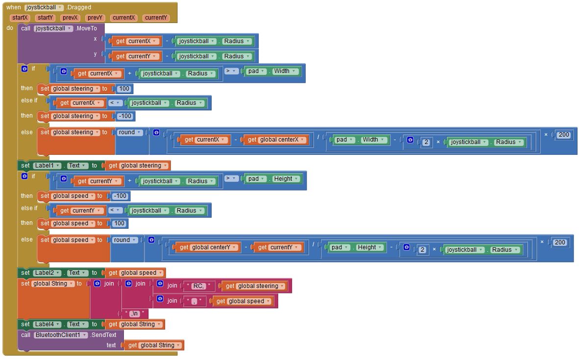
At the bottom, we see the orange pad with the blue joystickball in it. Now change into the Blocks-view to see the program. The heart of the program is a when-block that keeps track of the movements of your finger touching and dragging the blue joystickball:
The position of your finger is tracked in the two variables currentX and currentY and is used to calculate values for the two variables steering and speed (range: -100..0..+100). First the program checks if your finger is outside the pad and limits the values to +/- 100. If the finger is inside the pad, the program calculates values for steering and speed . Next, the program generates a command-string of the form:
The command starts with "RC" for remote control (the idea is that in the future, you might want to have more commands) followed by a comma. Then we send the values for steering and speed . The newline-character ('\n') at the end of the command is a signal to the Arduino that the command is complete. This command-string is sent over bluetooth to the Arduino. For your reference, the string is also displayed on the screen.
Reading bluetooth-commands into the Arduino
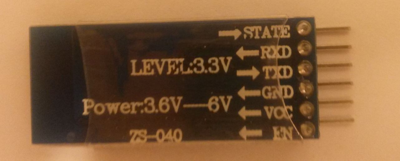
In order to read the Bluetooth command strings, we need to connect a HC-05 Bluetooth module. Have a look at your module:
Mine has 6 pins. We only need four pins. VCC is (positive) supply voltage and GND is ground. The module tolerates 6 Volt supply voltage, which means we can connect it to the arduino 5 Volt power pin. TXD and RXD are the serial signals. We have to cross the lines and connect TXD to arduino RXD (pin 0) and vice versa. Be careful: It states LEVEL: 3.3V which means that the RXD cannot be directly connected to the 5V arduino TXD (pin 1). We have to construct a voltage divider with three 1 kOhm resistors to produce an output voltage which is 2/3 of 5V (see schematics). On the other hand, the TXD signal of 3.3V can be directly connected to Arduino RXD. The Arduino will recognise 3.3 Volt as HIGH.
As pin 0 and 1 are shared with the USB port of your Arduino, you will have to disconnect the RXD and TXD signals from pin 0 and 1 while uploading the program over USB to the board. The upload won't work if you don't disconnect the cables.
Next, you have to pair the HC-05 module with your Android device. Switch Bluetooth on; start the app; press "Bluetooth connect"; make your phone visible and look for a device called HC-05 or similar. Select the device. You will be asked for a code. Press "1234". When you return to the joystick-screen, it should state "connected" in green.
Now, lets look at the code:
The string sent by the Android app is read into a special string-construct: a C-string with null-termination . (The 0-character tells the program that it has come to the end of the string). This is done by using the function Serial.readBytesUntil('\n', input, . ) , which reads from the serial interface (bluetooth) until it gets a newline-character ('\n'). That way, we keep reading bytes until we have a complete command in input :
A very efficient way to process input is the string token function, which cuts the string into parts using comma as a delimiter. The first call to strtok() returns "RC". The subsequent parts of the command are then read by passing NULL to strtok(). The returning values are stored in RCsteering and RCspeed . These variables are actually pointers to positions in input . The function atoi() converts them finally into integers. Now, we have:
We are almost done now. We have to multiply these values by 2.55 before we pass them on to our routine SetMotorControl() (Remember that motorspeed was in the range 0..255). Study the rest of the program in the CODE section, build the circuit and test your remote controlled Lego model!
Now that you have an Arduino controlling your Lego model, you might want to use that model as a robotics platform: add some ultrasonic ping sensors, program your own obstacle-avoiding logic and make your own self-driving robotic Mars rover. Or add more commands to the remote control and more functions to the model. But first, find a method for the Arduino to figure out that the model has traveled out of range of the bluetooth connection and stop the model. Tell me about your solution.
Soon enough, you will find out that a prototyping breadboard and loose cables are not a good idea for a moving model. Get yourself an adafruit motorshield with big terminal block connectors and rewire and reprogram. This will also free up digital signals that you can use for inputs instead. You might also consider a sensor shield for better connection of your sensors.
Let me know of your exiting projects!
Schematics
Github Lego-car-Arduino
Contains source code Arduino; Fritzing diagram; source code android app for upload to MIT app inventor

Давайте для начала немного вспомним историю развития технической серии и ответим на главные вопросы. Для чего разрабатывалось Lego Power Function, и какие задачи позволяют решить наборы?
Первые предпосылки к появлению полноценных решений для моторизации появились еще 1981 году с выходом 4.5 вольтового мотора в серии Лего Техник. Он был не таким удобным, как современные решения, но позволил привести в движение машины, что вызвало новый всплеск интереса к наборам серии. Модификации данного двигателя еще долгое время оставались единственным решением для энтузиастов, которым хотелось заставить свои модели двигаться и выполнять какие-то функции.
В 2007 году производитель представил полнофункциональную серию Lego Power Functions, благодаря которой огромный ряд современных наборов может приводиться в действие с помощью проводного или дистанционного управления. А для решения той или иной задачи есть целый набор двигателей соответствующего размера и мощности, а также светодиодное освещение. Но с появлением разнообразных решений у многих возникли сложности с выбором и не понимание, что же выбрать.

Как выбрать мотор Power Functions
В настоящее время на рынке имеются 4 модели моторов L, M, XL, Servo. И перед тем как выбрать один из них вам нужно подумать вот о чем:
- Для каких целей вы хотите использовать двигатель.
- Где должен располагаться двигатель, и какие возможности крепления присутствуют в вашей модели.
- Продумать трансмиссию или иными словами решить, как будет передаваться крутящий момент: от мотора к конечной точке моторизации, будь то винты, колеса, лебедки или валы, выполняющие «декоративную» роль.
Ответить на первый вопрос вам нужно будет самим. А с остальными двумя у вас не возникнет проблем, если вы прочитаете все до конца. Ведь в описаниях моделей мы будем приводить и оптимальные варианты использования двигателей.
8883 M (Medium) Motor. Средний мотор.
Средний мотор имеет относительно невысокую мощность и крутящий момент, потому использовать его в качестве двигателя для машин мы бы не рекомендовали. На выходе вы получите низкую скорость. Тем не менее, для совсем небольших моделей с малым весом, где не нужна высокая скорость, это решение все же может подойти. Также мотор 8883 M станет отличным решением для полноприводных моделей с установкой отдельных моторов на каждую ось.
Но все же лучше всего данная модель раскрывается при реализации рулевых систем, лебедок, пневмоклапанов, пневмокомпрессоров и в других задачах, не требующих высокой мощности и скорости вращения. Отличительной особенностью модели 8883 M является возможность крепления на площадку 6х2.
При использовании двигателя в рулевых системах и системах с высокой нагрузкой (где есть риск заклинивания) настоятельно рекомендуем применять белую шестеренку с проскальзывающим сердечником. Она надежно предохранит мотор и подвижные механизмы от поломок.

88003 L (Large) Motor. Большой мотор.
Универсальный легкий и компактный двигатель, обладающий высоким крутящим моментом и достаточной мощностью. Он отлично подойдет для установки в качестве основного и единственного двигателя на машины средних размеров, где привод осуществляется через центральную ось. При его использовании в больших и спортивных машинах все же рекомендуется устанавливать два мотора. Это даст большую мощность и скорость. А учитывая небольшие размеры и крепежные разъемы, с установкой пары движков 88003 L не возникнет никаких проблем.
Также данный мотор хорошо проявляет себя при использовании в рулевых системах крупной строительной техники. Но опять же, для решения данных задач не стоит забывать об использовании понижающих редукторов и белой защитной шестерни.
8882 XL (Extra Large) Motor. Экстра-большой мотор
Мощный и тяжелый низкооборотистый мотор идеально подходит для больших внедорожников, грузовиков и триальных машин. В общем, можно сказать, что он станет идеальным решением везде, где нужна беспрецедентная мощь, а скорость является второстепенной по значимости характеристикой.
Стоит учитывать, что в руках неопытного пользователя данный двигатель может стать причиной поломки передающих вращательный момент деталей. Поэтому его применение требует грамотного подхода и использования минимального количества звеней в цепи передачи крутящего момента.
Коротко можно сформулировать следующую рекомендацию: устанавливайте мотор 8882 XL как можно ближе к конечной точке вращения (колесам, валам и т.д.), используйте по возможности максимально прочные шестерни с крупными зубьями и короткие оси.
Стоит отметить, что данный мотор не подходит для построения скоростных моделей, в виду низкой скорости вращения.

88004 Servo Motor. Сервомотор.
Фанаты серии Техникс достаточно долго ждали данный мотор, так как он позволяет без лишней головной боли реализовать рулевое управление. В отличие от своих собратьев по серии данный двигатель осуществляет поворот центрального вала всего на 90 градусов в каждую сторону, а затем сам осуществляет возвращение в центральное положение, делая процесс поворота движущейся модели легким и приятным.
При использовании стандартного пульта пользователю доступно 3 положения вала мотора.
- 90 o по часовой стрелке;
- 90 o против часовой стрелки;
- Центральное положение (при отжатой кнопке управления и нажатии кнопки стоп/сброс).
При использовании пультов с плавной регулировкой, возможности двигателя расширяются, а пользователь может применять 14 позиций поворота (по 7 в каждую строну + центральное положение).
К особенностям серво мотора можно отнести наличие переднего и заднего соединения, что позволяет синхронно поворачивать задние и передние колеса.
Если управление мотором производится пультом с плавной регулировкой скорости, то и поворот вала будет происходить постепенно. При этом стоит отметить, что даже с обычным пультом поворот мотора под нагрузкой происходит достаточно плавно (без нагрузки заявлена скорость поворота равная 0.25с). Потому управление скоростными моделями может вызывать затруднение. Тем не менее, для новичков и для детей использование сервомотора в радиоуправляемых моделях будет лучшим решением.

Элементы питания
Для питания элементов Power Function используются специальные батарейные блоки.
Батарейный отсек Power Functions 8881 использует 6 пальчиковых батареек или аккумуляторов, которых в среднем хватает на 3-4 часа работы двигателей под нагрузкой.
Батарейный блок 88000 использует мизинчиковые батарейки и имеет меньшее время работы. Тем не менее, более компактные размеры блока позволят устанавливать его на небольшие модели.
Модель батарейного блока 8878 даст возможность существенно сэкономить на батарейках, так как содержит в себе мощный литий-ионный аккумулятор, обеспечивающий долгую работу двигателей и других элементов Lego Power Functions. А световой индикатор всегда предупредит о низком уровне заряда.
Управление
Для управления моторами и светодиодными элементами используются как стационарный переключатель с рычажками и кнопками, так и инфракрасный пульт, который работает на расстоянии до 4-х метров.
Стационарные модули управления подключаются к батарейному блоку и мотору через провода со сквозными защелками. Они имеют в своем распоряжении кнопки и рычажки, фиксирующиеся в определенных положениях. Каждое из двух боковых положений переключателя соответствует переднему или заднему ходу двигателя, а центральное состоянию покоя.
Инфракрасный пульт управления может работать на 4-х каналах. Это позволяет играть в одном помещении сразу нескольким детям и не мешать друг другу. Также иногда различные каналы могут понадобиться для управления моделью с множеством моторизированных блоков.
Читайте также: